SA-K7N SOUNDER WITH VISUAL ALARM DEVICE FOR FIRE ALARM SYSTEMS HOLDS DOCUMENTS ISSUED BY CNBOP-PIB:

Use:
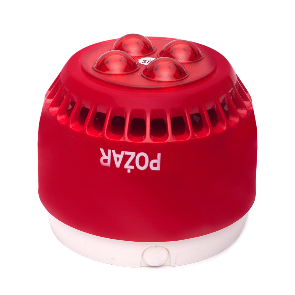
The acoustic-optical alarm device SA-K7N is intended for signalling of fire inside buildings.
Construction:
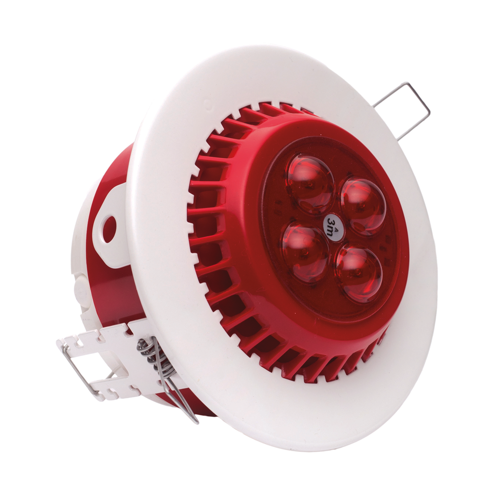
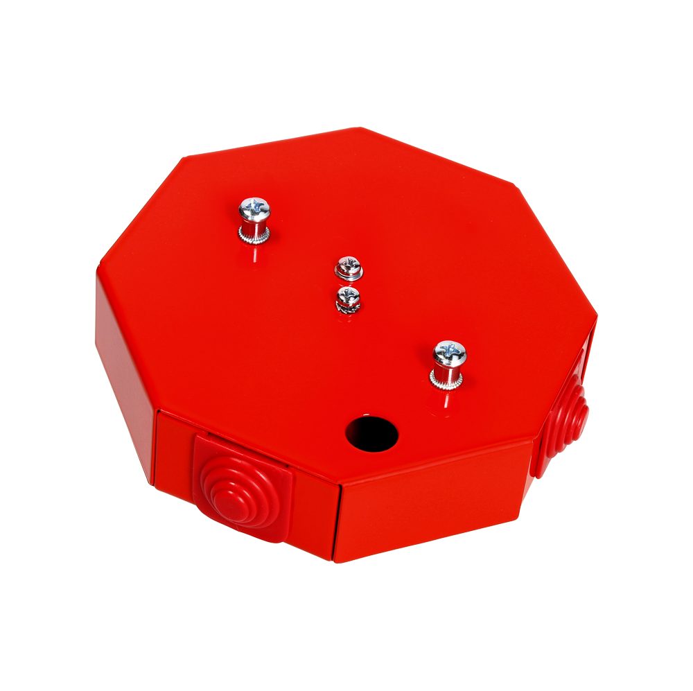
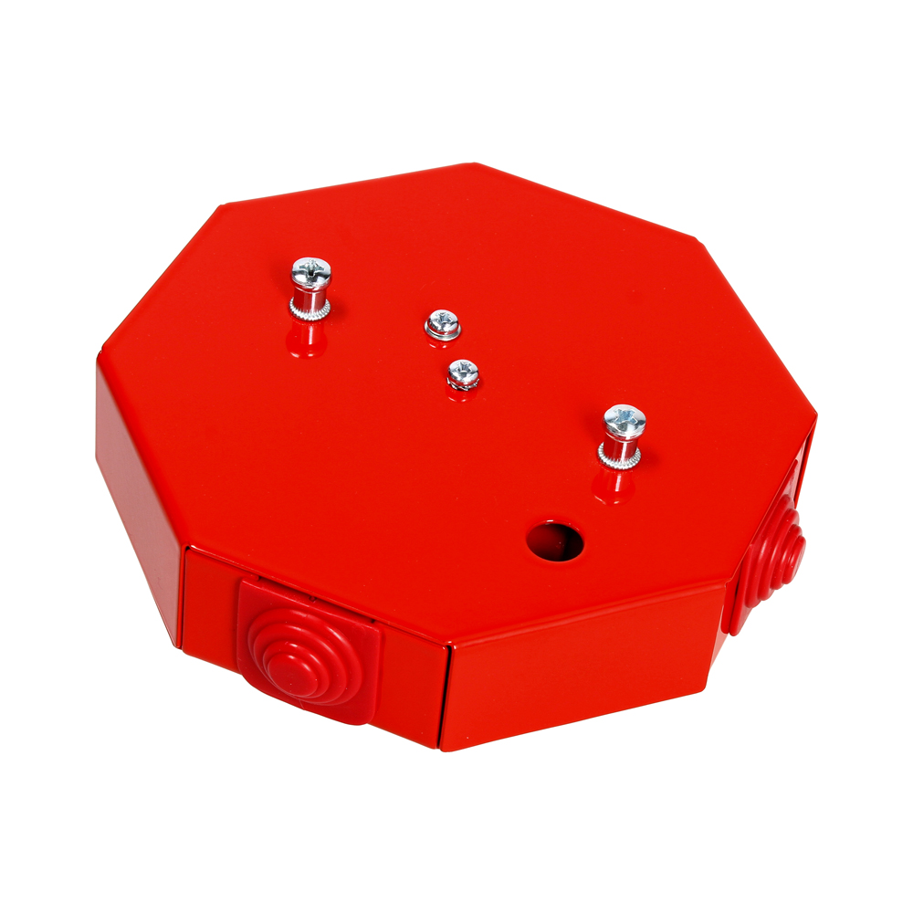
The signalling device is equipped with housing made of non-combustible material, enclosing electronic components. Upper part of the housing contains light source – power LEDs. SA-K7N signalling devices are equipped with supply connector, WSD switch connector and six-position microswitch located in cover, by means of which operating mode of signallig device can be selected – either “master” or “slave”, and also tone pattern.
SA-K7N acoustic-optical alarm device is made in three variants: 9m, 6m and 3m. Depending on version of signalling device, coverage area changes (the area, in which light intensity is higher than 0.4 lx). The signalling device meets requirements of EN 54-23, EN 54-3 standards. SA-K7N acoustic-optical alarm device enables creation of synchronously operating signalling devices’ network (synchronization of acoustic and optical part with use of additional line). SA-K7N signalling device is adapted to co-operation with WSD-1 switch.
The acoustic part of signalling device enables volume adjustment and use of linear volume increase option (from approx. 70 dB up to 100 dB @ 1 m). Adjustment of volume is done by means of potentiometer located in cover of signalling device. While the option of progressive volume increase is switched on by shifting the microswitch to adequate position.
Operating principle of the signalling device:
After the supply voltage has been applied to the SA-K7N signalling device, it generates pulse optical signal, having light up time shorter than 0.2 s and acoustic signal conforming to current settings. Frequency of generated optical signal is equal to 0.56 Hz. Power LEDs, placed in enclosure (lampshade) forming an optical system, are light generating elements. The SA-K7N signalling device enables creation of synchronously operating signalling devices’ network (the acoustic and optical parts are being synchronized).
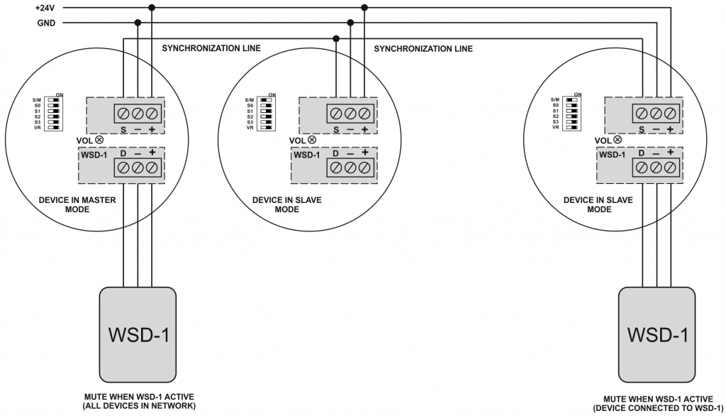
Creation of signalling device’s network in synchronous operation:
It is necessary to configure mode of signalling device operation prior to proceeding with creating a network of signalling devices. There is six -positions of microswitch, located in the cover of signalling device, which when moved from S/M position to ON position, sets “master” operating mode, while the “OFF” position sets the “slave” operating mode.
Only one “master” signalling device is allowed in any network, which is responsible for generating of synchronization pulses. The remaining signalling devices must be set to “slave” operating mode. Improper setting of operating mode will result in improper operation of signalling devices’ network.
Designations:
| SA-K7N/3m | Acoustic – optical fire signalling device SA-K7N of 3m main installation height |
| SA-K7N/6m | Acoustic – optical fire signalling device SA-K7N of 6m main installation height |
| SA-K7N/9m | Acoustic – optical fire signalling device SA-K7N of 9m main installation height |
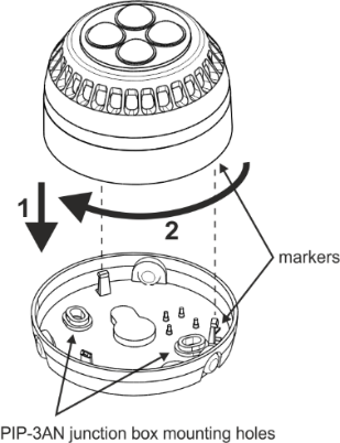
Opening:
To open the signalling device: screw out the screw locking the base, turn the shade anticlockwise while holding the base, then separate the shade and the base.
Closing:
To close the signalling device: fit together the markers. After that put together the device and turn in the direction marked with an arrow (the sequence in the drawing). On closing, lock the base by screwing in the locking screw.